|
Size: 4864
Comment:
|
← Revision 107 as of 2024-05-08 07:27:37 ⇥
Size: 7356
Comment:
|
| Deletions are marked like this. | Additions are marked like this. |
| Line 1: | Line 1: |
| ## page was renamed from WWK | |
| Line 5: | Line 4: |
| = WWK-Wiki am IfM = Am Windwellenkanal der Uni Hamburg werden grundlegende Untersuchungen durchgeführt zu Wechselwirkungen an der Wasseroberfläche und zu ihrer Fernerkundung. Flüsse von Energie, Impuls, Gas und Wärme, sowie die verantwortlichen kleinskaligen Prozesse, können gezielt variiert und untersucht werden. Hierzu finden regelmäßig Messkampagnen am Windwellenkanal statt, deren Ergebnisse wertvolle Beiträge zur Entwicklung von Theorien zu Wechselwirkungen zwischen Ozean und Atmosphäre sowie zur (Radar-) Fernerkundung der Meeresoberfläche liefern. |
|
| Line 8: | Line 5: |
| {{attachment:UHH_WWK_Interior.jpg}} | = The Wind-Wave Tank of the University of Hamburg = At U Hamburg's wind-wave tank basic research is perfomed on air-sea interactions and their remote sensing. Fluxes of energy, momentum, gas and heat, along with the underlying small-scale processes, can be varied and studied. Frequent experimental campaigns are performed aid in the development of new theories on air-sea interactions and on the radar remote sensing of wind-roughended sea surfaces.<<BR>><<BR>> |
| Line 10: | Line 8: |
| ''Das Innere des Windwellenkanals der Uni Hamburg, von der Leeseite aus gesehen. Foto (c) M. Steinmetz 2002.'' | . {{attachment:WWK.jpg|UHH's wind-wave tank|width=60%}} . ~-''U Hamburg's wind-wave tank.''-~<<BR>><<BR>> |
| Line 12: | Line 11: |
| Der Windwellenkanal wurde Anfang der 1970er Jahre gebaut und befindet sich auf dem Gelände der [[http://www.baw.de/vip/en/departments/department_k/index.html|Bundesanstalt für Wasserbau]], Außenstelle Küste, in Hamburg-Rissen. Der wassergefüllte Teil ist 24 m lang und 1 m breit, das luftgefüllte Volumen ist 1 m hoch. Der Tank ist mit Frischwasser gefüllt, mit einem Radialgebläse können Windgeschwindigkeiten bis ca. 25 m/s erzeugt werden und mit einer Wellenklappe lange Wellen mit Frequenzen zwischen 0.7 Hz und 2.5 Hz. | The wind_wave tank was built in the early 1970s and is located in a hall at the Federal Institute of Waterways Engineering in Hamburg-Rissen. The water-filled part of the large facility is 24 m long and 1 m wide, and the air volume is 1 m high. The tank is filled with fresh water, a radial blower is used to generate wind speeds up to 25 m/s and a wave flap to generate long waves of frequencies between 0.7 Hz and 2.5 Hz.<<BR>><<BR>> |
| Line 14: | Line 13: |
| {{attachment:UHH_WWK_Sketch.jpg}} | . {{attachment:WWK_Regen2_Ziff.jpg|Sketch of the wwt|width=80%}} . ~-''Schematic side view of the wind-wave tank during campaigns with artificial rain; 1: wind tunnel; 2: beach; 3: radar antennas; 4: wave height and slope sensors; 5: laser optics; 6: rain generator; 7: honeycomb; 8: wave flap; 9: radial blower.''-~<<BR>><<BR>> |
| Line 16: | Line 16: |
| ''Schematische Seitenansicht des Windwellenkanals. 1:Diffusor, 2:Strand, 3:Radarantennen, 4:Wellhöhen- und -neigungssensoren, 5:Regengenerator, 6:Laseroptik, 7:Mikrowellenabsorber, 8:Flügelrad-Anemometer, 9:Wabenscheibe, 10:Wellenklappe, 11:Radialgebläse.'' | The wind-wave tank is very well suited for experiments under controlled environmental conditions. E.g., in order to simulate biogenic films on the sea surface chemical model substances can be deployed, which form surface films of only one molecule thickness. The impact of those films on the small-scale wave and current field, and on the backscattered radar power, can be studied in great detail. Taking advantage of its flexible usage, the wind-wave tank can be well used to study a wealth of scientific aspects and to help in interpreting remotely sensed data.<<BR>><<BR>> |
| Line 18: | Line 18: |
| Ende der 1990er Jahre wurde ein Regengenerator installiert, mit dessen Hilfe auf einer Fläche von 2.3 qm Starkregen bis zu 300 mm/h erzeugt werden kann. Mitte der 2000er Jahre wurde der Windwellenkanal durch Zufügen einer Luft-Rezirkulation gegen die Umgebung vollständig (also luft- und wasserseitig) abgedichtet, sodasss umfangreiche Gasaustauschmessungen durchgeführt werden konnten. | . {{attachment:WWK-Wind.jpg|windwaves|width=40%}} {{attachment:WWK-WindSlick.jpg|windwaves and slick|width=40%}} . ~-''Photographs showing the damping effect of a surfactant; left: wind-generated waves at 5m/s; right: same wind speed, but upper part covered by a surfactant.''-~<<BR>><<BR>> |
| Line 20: | Line 21: |
| {{attachment:UHH_WWK_windwaves.gif}} | In the late 1990s, a rain generator was developed and installed to generate heavy rain of up to 300 mm/h on an area of 2.3 m². In the mid 2000s, an air re-circulation was added for comprehensive gas exchange measurements.<<BR>><<BR>> |
| Line 22: | Line 23: |
| ''Seitenansicht winderzeugter Wellen bei unterschiedlichen WIndgeschwindigkeiten.'' | . {{attachment:WWK-Rain.jpg|rain drops impinging on the water suface|width=50%}} . ~-''Photograph showing splash products caused by impinging rain drops.''-~<<BR>><<BR>> |
| Line 24: | Line 26: |
| Der Windwellenkanal ist hervorragend geeignet für Experimente, die genau definierte Umweltbedingungen erfordern. So können z.B. zur Simulation biogener Filme auf dem Meer Oberflächenfilme, die nur eine Moleküllage dick sind, erzeugt und ihre Wirkung auf das Wellenfeld studiert werden. Oder es kann Starkregen mit konstanten Regenraten und -tropfengrößen erzeugt werden, um genau zu untersuchen, wie er das Radarsignal oder den Gasaustausch an der Wasseroberfläche beeinflusst. Durch seine flexible Nutzung kann der Windwellenkanal daher eingesetzt werden, um vielfältige wissenschaftliche Fragestellungen gezielt zu bearbeiten und die Interpretation von Fernerkundungsdaten so zu erleichtern. | Since the mid 1980s, dedicated experiments at U Hamburg's wind-wave tank have been used to generate a better understanding of the radar backscattering from the ocean surface. The radar backscatter depends on the surface roughness, which is a function of wind speed, but which may also be increased by heavy rain, or decreased by marine surface films. Those effects can well be simulated in the wind-wave tank of the University of Hamburg.<<BR>><<BR>> |
| Line 26: | Line 28: |
| {{attachment:UHH_WWK_SARexample.gif}} | . {{attachment:UHH_WWK_SARexample.jpg|SAR image|width=60%}} . ~-''Synthetic Aperture Radar (SAR) Image of the South China Sea, acquired from the European ERS-1 satellite on 14 May 1998 at 02:52 UTC ((c) ESA). Bright patches in the lower left part were caused by heavy rain, the elongated dark patches in the upper left part by marine surface films. Image size 100 km x 110 km.''-~<<BR>><<BR>> |
| Line 28: | Line 31: |
| ''Synthetik-Apertur-Radar (SAR) Aufnahme des Südchinesischen Meers, die von Bord des Europäischen UMweltsatelliten ERS-1 aus am 14. Mai 1998 um 0252 UTC gemacht wurde ((c) ESA). DIe hellen Flecken im unteren linken Bereich werden durch Starkregen verursacht, die länglichen dunklen Bereiche im oberen Bereich durch marine Oberflächenfilme. Bildgröße 100 km x 105 km.'' | More recently, dedicated experiments on turbulent flows on either sides of the wind-roughened water surface were performed, deploying state-of-the-art laser sensors. Experiments with a Laser Doppler Velocimeter (LDV) allowed measuring time series of two-dimensional currents in the air and upper water layer, just millimeters above and below the water surface, respectively.<<BR>><<BR>> |
| Line 30: | Line 33: |
| ---- === Ozeanische Messübungen am WWK === [[FEW3O/WWK/WWKPraktikum|{{attachment:OzMess_b.jpg|FEW3O/WWK/WWKPraktikum|height="30"}}]] [[FEW3O/WWK/WWKPraktikum|Interne Seiten]] für die Teilnehmer an den Messübungen. |
. {{attachment:WWK-LDV.jpg|LDV|width=50%}} . ~-''Photograph taken during measurements with the Laser Doppler Velocimeter.''-~<<BR>><<BR>> The knowledge of small-scale processes at wind-roughened water surfaces is key to our undertanding of exchange processes across the water surface, including the transfer of so-called greenhouse gases. When a fluorescent dye is added to the water in the wind-wave tank, detailed studies of the dynamic water surface can be performed. Laser-Induced Fluorescence (LIF) uses a laser-generated light sheet to visualize the two-dimensional surface of wind-generated waves. Deploying high-speed cameras we monitor the generation of gravity-capillary waves, along with small-scale breaking events that give rise to changes in the wave spectra and in the local air and water flows in the vicinity of the water surface.<<BR>><<BR>> . {{attachment:WWK-LIF.jpg|LIF|width=60%}} . ~-''Laser-Induced Fluorescence (LIF) measurements of a wavy water surface.''-~<<BR>><<BR>> Particle Image Velocimetry (PIV), in combination with LIF, provides high-resolution measurements of velocity fields and underwater turbulent dynamics within the first millimeters above and below the water surface in the presence (and absence) of surfactants. At the wind-wave tank of the University of Hamburg we jointly use PIV and LIF techniques, along with various wave height and slope sensors, to get a full picture of the turbulent dynamics above and below the wavy water surface.<<BR>><<BR>> . {{attachment:WWK-PIV.jpg|LIF|width=50%}} . ~-''Particle Image Velocimetry (PIV) measurements in U Hamburg's wind-wave tank.''-~<<BR>><<BR>> |
| Line 42: | Line 55: |
| . {{attachment:WWT_Chemistry.gif|FEW3O/WWK/WWT_Slicksdamping}} [[FEW3O/WWK/WWT_Slicksdamping|Sea slicks and their chemical properties]] | . {{attachment:WWT_Chemistry.gif|WWT_Chemistry}} [[KFEW3O/WWK/WWT_Chemistry|Sea slicks and their chemical properties]] |
| Line 44: | Line 57: |
| . |{{attachment:WWT_Gastransfer.gif|FEW3O/WWK/WWT_Slicksdamping}} [[FEW3O/WWK/WWT_SlicksdampingGas transfer across the water-air interface]] | . {{attachment:WWT_Gastransfer.gif|WWT_Gastransfer}} [[KFEW3O/WWK/WWT_Gastransfer|Gas transfer across the water-air interface]] |
| Line 46: | Line 59: |
| . {{attachment:WWT_Slicksdamping.gif|FEW3O/WWK/WWT_Slicksdamping}} [[FEW3O/WWK/WWT_Slicksdamping|Monomolecular surface films: wave damping and radar backscattering]] | . {{attachment:WWT_Slicksdamping.gif|WWT_Slicksdamping}} [[KFEW3O/WWK/WWT_Slicksdamping|Monomolecular surface films: wave damping and radar backscattering]] |
| Line 48: | Line 61: |
| . {{attachment:WWT_Boundwaves.gif|FEW3O/WWK/WWT_Slicksdamping}} [[FEW3O/WWK/WWT_Slicksdamping|Bound and free gravity-capillary waves]] | . {{attachment:WWT_Boundwaves.gif|WWT_Boundwaves}} [[KFEW3O/WWK/WWT_Boundwaves|Bound and free gravity-capillary waves]] |
| Line 50: | Line 63: |
| . {{attachment:WWT_Heavyrain.gif|FEW3O/WWK/WWT_Slicksdamping}} [[FEW3O/WWK/WWT_Slicksdamping|Experiments with heavy rain]] | . {{attachment:WWT_Heavyrain.gif|WWT_Heavyrain}} [[KFEW3O/WWK/WWT_Heavyrain|Experiments with heavy rain]] |
| Line 52: | Line 65: |
| . {{attachment:WWT_Rainturbulence.gif|FEW3O/WWK/WWT_Slicksdamping}} [[FEW3O/WWK/WWT_Slicksdamping|Rain-induced sub-surface turbulence]] | . {{attachment:WWT_Rainturbulence.gif|WWT_Rainturbulence}} [[KFEW3O/WWK/WWT_Rainturbulence|Rain-induced sub-surface turbulence]] |
| Line 56: | Line 69: |
| [[FEW3O/WWK/WWKintern|{{attachment:intern_r.jpg|FEW3O/WWK/WWKintern|height="30"}}]] ...zu den internen WWK-Seiten geht's [[FEW3O/WWK/WWKintern|hier]]. | === Ongoing Research === . . {{attachment:WWT_PIV.gif|WWT_PIV}} [[KFEW3O/WWKBASS|Momentum and energy fluxes]] . |
| Line 58: | Line 74: |
| [[FEW3O|{{attachment:FEW3O_l.jpg|FEW3O|height="30"}}]] ... zurück zur [[FEW3O|FEW3O-Seite]]... | ---- === Practicals: ''Ozeanische Messübungen am WWK'' === . {{attachment:KFEW3O/Grünpfeil.jpg||height=30}} [[ozmess|{{attachment:KFEW3O/OzMess_b.jpg|Ozeanische Messübungen|height="30"}}]] ...practicals ([[ozmess|for participants only]]) ----- . {{attachment:KFEW3O/Grünpfeil.jpg||height=30}} [[KFEW3O/WWK/WWKintern|{{attachment:KFEW3O/intern_l.jpg|WWKintern|height="30"}}]] ...internal WWK pages [[KFEW3O/WWK/WWKintern|this way]]. . {{attachment:KFEW3O/Grünpfeil.jpg||height=30}} [[KFEW3O|{{attachment:KFEW3O/KFEW3O_l.jpg|KFEW3O|height="30"}}]]... back to the [[KFEW3O|main KFEW3O page]]... |
The Wind-Wave Tank of the University of Hamburg
At U Hamburg's wind-wave tank basic research is perfomed on air-sea interactions and their remote sensing. Fluxes of energy, momentum, gas and heat, along with the underlying small-scale processes, can be varied and studied. Frequent experimental campaigns are performed aid in the development of new theories on air-sea interactions and on the radar remote sensing of wind-roughended sea surfaces.
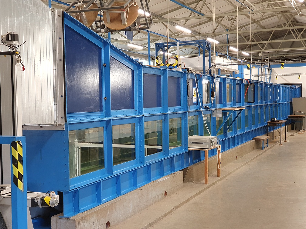
U Hamburg's wind-wave tank.
The wind_wave tank was built in the early 1970s and is located in a hall at the Federal Institute of Waterways Engineering in Hamburg-Rissen. The water-filled part of the large facility is 24 m long and 1 m wide, and the air volume is 1 m high. The tank is filled with fresh water, a radial blower is used to generate wind speeds up to 25 m/s and a wave flap to generate long waves of frequencies between 0.7 Hz and 2.5 Hz.

Schematic side view of the wind-wave tank during campaigns with artificial rain; 1: wind tunnel; 2: beach; 3: radar antennas; 4: wave height and slope sensors; 5: laser optics; 6: rain generator; 7: honeycomb; 8: wave flap; 9: radial blower.
The wind-wave tank is very well suited for experiments under controlled environmental conditions. E.g., in order to simulate biogenic films on the sea surface chemical model substances can be deployed, which form surface films of only one molecule thickness. The impact of those films on the small-scale wave and current field, and on the backscattered radar power, can be studied in great detail. Taking advantage of its flexible usage, the wind-wave tank can be well used to study a wealth of scientific aspects and to help in interpreting remotely sensed data.
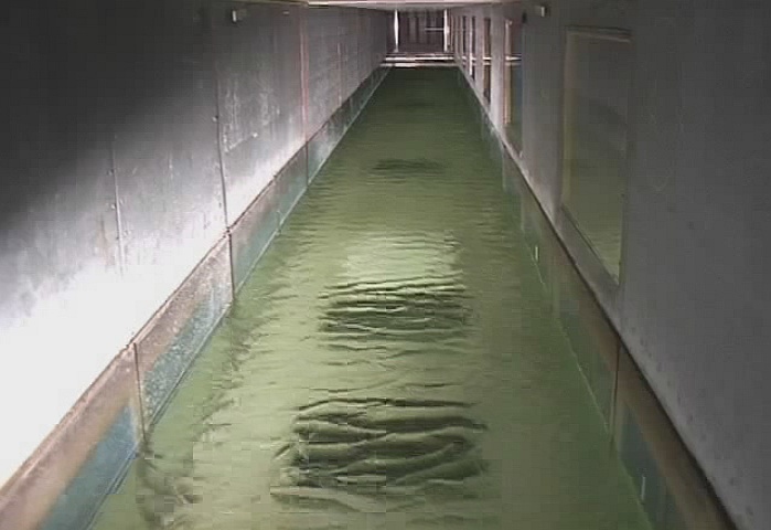
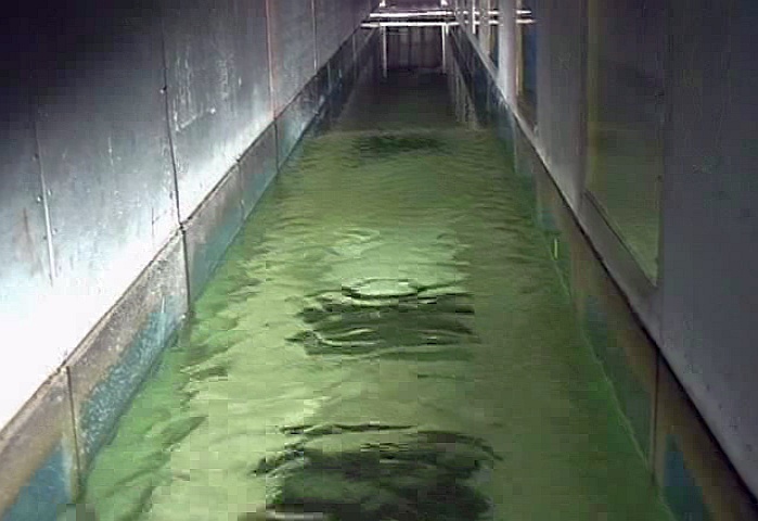
Photographs showing the damping effect of a surfactant; left: wind-generated waves at 5m/s; right: same wind speed, but upper part covered by a surfactant.
In the late 1990s, a rain generator was developed and installed to generate heavy rain of up to 300 mm/h on an area of 2.3 m². In the mid 2000s, an air re-circulation was added for comprehensive gas exchange measurements.
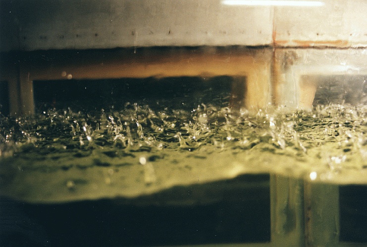
Photograph showing splash products caused by impinging rain drops.
Since the mid 1980s, dedicated experiments at U Hamburg's wind-wave tank have been used to generate a better understanding of the radar backscattering from the ocean surface. The radar backscatter depends on the surface roughness, which is a function of wind speed, but which may also be increased by heavy rain, or decreased by marine surface films. Those effects can well be simulated in the wind-wave tank of the University of Hamburg.
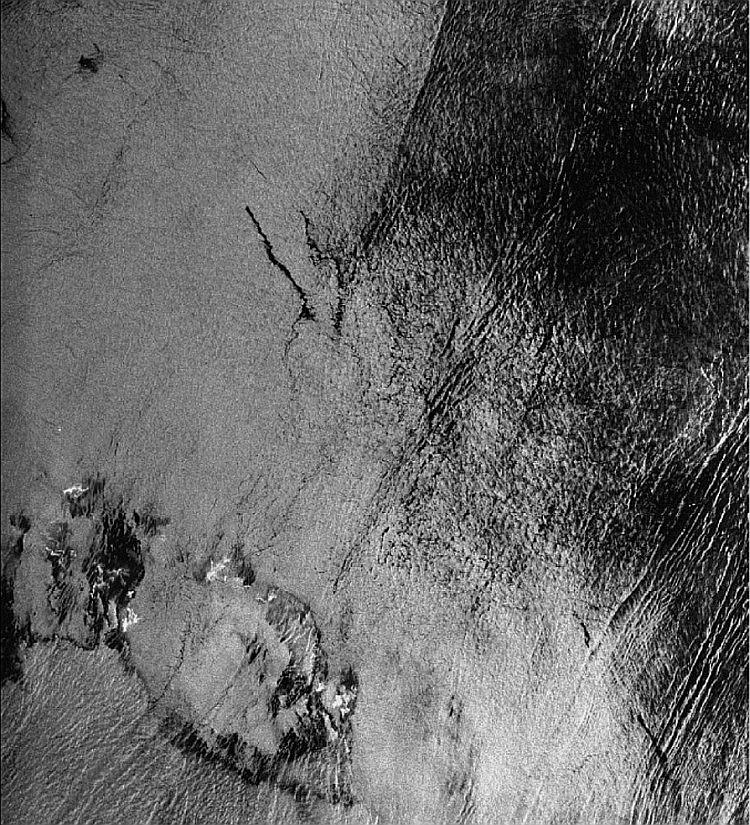
Synthetic Aperture Radar (SAR) Image of the South China Sea, acquired from the European ERS-1 satellite on 14 May 1998 at 02:52 UTC ((c) ESA). Bright patches in the lower left part were caused by heavy rain, the elongated dark patches in the upper left part by marine surface films. Image size 100 km x 110 km.
More recently, dedicated experiments on turbulent flows on either sides of the wind-roughened water surface were performed, deploying state-of-the-art laser sensors. Experiments with a Laser Doppler Velocimeter (LDV) allowed measuring time series of two-dimensional currents in the air and upper water layer, just millimeters above and below the water surface, respectively.
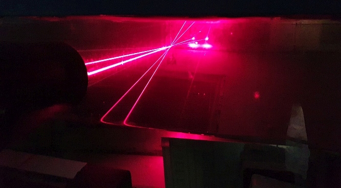
Photograph taken during measurements with the Laser Doppler Velocimeter.
The knowledge of small-scale processes at wind-roughened water surfaces is key to our undertanding of exchange processes across the water surface, including the transfer of so-called greenhouse gases. When a fluorescent dye is added to the water in the wind-wave tank, detailed studies of the dynamic water surface can be performed. Laser-Induced Fluorescence (LIF) uses a laser-generated light sheet to visualize the two-dimensional surface of wind-generated waves. Deploying high-speed cameras we monitor the generation of gravity-capillary waves, along with small-scale breaking events that give rise to changes in the wave spectra and in the local air and water flows in the vicinity of the water surface.

Laser-Induced Fluorescence (LIF) measurements of a wavy water surface.
Particle Image Velocimetry (PIV), in combination with LIF, provides high-resolution measurements of velocity fields and underwater turbulent dynamics within the first millimeters above and below the water surface in the presence (and absence) of surfactants. At the wind-wave tank of the University of Hamburg we jointly use PIV and LIF techniques, along with various wave height and slope sensors, to get a full picture of the turbulent dynamics above and below the wavy water surface.
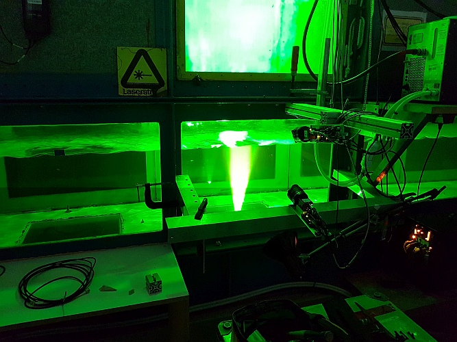
Particle Image Velocimetry (PIV) measurements in U Hamburg's wind-wave tank.
Description
Description of UHH's wind-wave tank (M. Gade, 2003)
Previous Research
Ongoing Research
Practicals: ''Ozeanische Messübungen am WWK''

 ...practicals (for participants only)

 ...internal WWK pages this way.
 ... back to the main KFEW3O page...


